
information
INFORMATIONHOTLINE
+86-0531-85667509 Address:Huaiyin District of Jinan City Road, No. 24566 ten
T e l:+86-0531-85667509
F a x:86-0531-85667508
E-mai:warwickpump@gmail.com
T e l:+86-0531-85667509
F a x:86-0531-85667508
E-mai:warwickpump@gmail.com
News Center
System Design of the molten salt pump
release time:2016/10/31 clicks:
The modular cascade thermal energy storage system (MCTES) is a three-tank sensible heat storage plant using molten nitrate salt as thermal storage and heat transfer fluid. It is designed to accept heat from an electric heater at a rate of 75 kilowatts (kW) for 6 hours, store the 450 kilowatt hours (kWh) of heat for 12 hours, and reject heat at a rate of 75 kW for 6 hours through a simulated steam generator. The salt is operated between the temperatures of 554°F (290°C) and 1049°F (565°C).
The basic operation of a three-tank system is outlined in Figure 3. At the start of the day, if tanks 2 and 3 are full of cold fluid and tank 1 is empty, cold fluid is withdrawn from tank 2, heated in the electric heater and placed in tank 1, which is empty. At about midday, tank 1 is full of hot fluid and tank 2 is empty. Cold fluid is then withdrawn from tank 3 and after heating is deposited in tank 2. At the end of the day, the fully charged multi-tank storage system contains hot fluid in tanks 1 and 2.
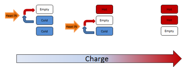 Figure 3: Flow Diagram of the Charging of a Three-Tank Thermal Storage System
The molten salt is transported across the different parts of the system using vertical cantilever pumps. Two salt pumps are required in order for the system to operate (a hot and cold pump) as is the case with a traditional design. In the proposed modular design, the pumps are located in sumps that are external to the molten salt storage tanks. All the tank drains are manifolded and connected to the lower part of each pump sump. A valve at each tank drain and at each pump sump inlet directs the flow of salt out of either tank, and into either pump sump using gravity as a driving force. Only one drain valve and one sump inlet valve is open at a given time, which ensures that exactly one pump is supplied with salt from exactly one tank.
Following the heat input or heat rejection process, the salt is returned to one of the salt tanks in a similar fashion. All the tank return lines are manifolded and a valve in each tank return line controls the flow of salt into each tank.
The Process Flow Diagram (PFD) of the three-tank thermal energy system (TES) is presented in Figure 4, identifying heat flows into and out of the system, with corresponding mass flow rates of molten salt and cooling air to charge and discharge the system. The major equipment, shown on this diagram, includes three tanks, two pumps, two heat exchangers, and ten control valves. The “Piping and Instrumentation Diagram” shown in Appendix A was identifies all major equipment and interconnecting piping, as well as all the instrumentation required to monitor and control the system. It also shows the locations of the control valves, which are the primary mechanism for controlling the flow of salt to and from either one of the storage tanks in the system.
The basic operation of a three-tank system is outlined in Figure 3. At the start of the day, if tanks 2 and 3 are full of cold fluid and tank 1 is empty, cold fluid is withdrawn from tank 2, heated in the electric heater and placed in tank 1, which is empty. At about midday, tank 1 is full of hot fluid and tank 2 is empty. Cold fluid is then withdrawn from tank 3 and after heating is deposited in tank 2. At the end of the day, the fully charged multi-tank storage system contains hot fluid in tanks 1 and 2.
The molten salt is transported across the different parts of the system using vertical cantilever pumps. Two salt pumps are required in order for the system to operate (a hot and cold pump) as is the case with a traditional design. In the proposed modular design, the pumps are located in sumps that are external to the molten salt storage tanks. All the tank drains are manifolded and connected to the lower part of each pump sump. A valve at each tank drain and at each pump sump inlet directs the flow of salt out of either tank, and into either pump sump using gravity as a driving force. Only one drain valve and one sump inlet valve is open at a given time, which ensures that exactly one pump is supplied with salt from exactly one tank.
Following the heat input or heat rejection process, the salt is returned to one of the salt tanks in a similar fashion. All the tank return lines are manifolded and a valve in each tank return line controls the flow of salt into each tank.
The Process Flow Diagram (PFD) of the three-tank thermal energy system (TES) is presented in Figure 4, identifying heat flows into and out of the system, with corresponding mass flow rates of molten salt and cooling air to charge and discharge the system. The major equipment, shown on this diagram, includes three tanks, two pumps, two heat exchangers, and ten control valves. The “Piping and Instrumentation Diagram” shown in Appendix A was identifies all major equipment and interconnecting piping, as well as all the instrumentation required to monitor and control the system. It also shows the locations of the control valves, which are the primary mechanism for controlling the flow of salt to and from either one of the storage tanks in the system.